Portable extinguishers

There are four principal types of portable extinguishers usually found on board ships. These are the soda-acid, foam, dry powder and carbon dioxide extinguishers. Soda-acid
extinguisher
The container of this extinguisher holds a sodium bicarbonate solution. The screw-on cap contains a plunger mechanism covered by a safety guard. Below the plunger is a glass phial containing sulphuric acid. When the plunger is struck the glass phial is broken and the acid and sodium bicarbonate mix.
The resulting chemical reaction produces carbon dioxide gas which pressurises the space above the liquid forcing it out through the internal pipe to the nozzle. This extinguisher is used for Class A fires and will be found in accommodation areas.
Must read ➤ All-Electric Steering In Marine Engineering
Foam extinguisher—chemical
The main container is filled with sodium bicarbonate solution and a long inner polythene container is filled with aluminium sulphate. The inner container is sealed by a cap held in place by a plunger. When the plunger is unlocked by turning it, the cap is released.

The extinguisher is then inverted for the two liquids to mix. Carbon dioxide is produced by the reaction which pressurises the container and forces out the foam.
Foam extinguisher—mechanical
The outer container in this case is filled with water. The central container holds a carbon dioxide charge and a foam solution. A plunger mechanism with a safety guard is located above the central container. When the plunger is depressed the carbon dioxide is released and the foam solution and water mix.
They are then forced out through a special nozzle which creates the mechanical foam. This extinguisher has an internal pipe and is operated upright. Foam extinguishers are used on Class B fires and will be located in the vicinity of flammable liquids.
Carbon dioxide extinguisher
237 A very strong container is used to store liquid carbon dioxide under pressure. A central tube provides the outlet passage for the carbon dioxide which is released either by a plunger bursting a disc or a valve operated by a trigger.
The liquid changes to a gas as it leaves the extinguisher and passes through a swivel pipe or hose to a discharge horn. Carbon dioxide extinguishers are mainly used on Class B and C fires and will be found in the machinery space, particularly near electrical equipment.

The carbon dioxide extinguisher is not permitted in the accommodation since, in a confined space, it could be lethal.
Dry powder extinguishers

The outer container contains sodium bicarbonate powder. A capsule of carbon dioxide gas is located beneath a plunger mechanism in the central cap.
On depressing the plunger the carbon dioxide gas forces the powder up a discharge tube and out of the discharge nozzle.
The dry powder extinguisher can be used on all classes of fire but it has no cooling effect. It is usually located near electrical equipment in the machinery space and elsewhere on the ship.
Maintenance and testing
All portable extinguishers are pressure vessels and must therefore be regularly checked. The soda-acid and foam extinguisher containers are initially tested to 25 bar for five minutes and thereafter at four-year intervals to 20 bar.
The carbon dioxide extinguisher is tested to 207 bar initially every 10 years and after two such tests, every five years. The dry powder extinguisher is tested to 35 bar once every four years.
Most extinguishers should be tested by discharge throughout one to five years, depending on the extinguisher type, e.g. soda-acid and dry powder types 20% discharged per year, foam types 50% discharged per year.
Carbon dioxide extinguishers should be weighed every six months to check for leakage. Where practicable the operating mechanisms of portable extinguishers should be examined every three months. Any plunger should be checked for free movement, vent holes should be clear and cap threads lightly greased.
Most extinguishers with screw-on caps have several holes in the threaded region. These are provided to release pressure before the cap is taken off: they should be checked to be clear.
Fixed installations
fire main
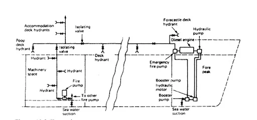
A variety of different fixed fire fighting installations exist, some of which are specifically designed for certain types of ships. A selection of the more general installations will now be outlined. Fire main A seawater supply system for fire hydrants is fitted to every ship. Several pumps in the engine room will be arranged to supply the system, their number and capacity being dictated by legislation (Department of Transport for UK registered vessels).
An emergency fire pump will also be located remote from the machinery space and with independent A system of hydrant outlets, each with an isolating valve, is located around the ship, and hoses with appropriate snap-in connectors are strategically located together with nozzles.
These nozzles are usually of the jet/spray type providing either type of discharge as required. AH, the working areas of the ship are thus covered, and a constant supply of seawater can be brought to bear at any point to fight a fire. While sea water is best used as a cooling agent in fighting Class A fires it is possible, if all else fails, to use it to fight Class B fires.
The jet/spray nozzle would be adjusted to provide a fine water spray which could be played over the fire to cool it without spreading. An international shore connection is always carried on board the ship. This is a standard-size flange which is fitted with a coupling suitable for the ship's hoses. The flange is slotted to fit any shore-side fire main and enable water to be brought on board a ship lying alongside.
Automatic water spray

The complete installation is divided into several sections, each containing about 150 to 200 sprinklers and having an alarm valve. When one or more sprinklers operate water flows through the section valve sounds an alarm and also provides a visual display identifying the section containing the fire.
In the machinery space, the sprinkler heads are known as 'sprayers' and have no quartzoid bulb. Also, the section valves are manually operated to supply water to the sprayers. The system is pressurised by compressed air with a saltwater pump arranged to cut in automatically if the pressure drops.
The accommodation and machinery space systems may be combined by a valve which is normally kept locked shut. The system should be regularly checked by creating fault conditions at the various section control valves by opening a test valve and checking for audible and visual alarms.

The automatic spray or sprinkler system provides a network of sprinkler heads throughout the protected spaces. This system may be used in accommodation areas, and in machinery spaces with certain variations in the equipment used and the method of operation. The accommodation areas are fitted with sprinkler heads which both detect and extinguish fires.
The sprinkler head is closed by a quartzoid bulb which contains a liquid that expands considerably on heating. When excessively heated the liquid expands, shatters the bulb and water will issue from the sprinkler head. A deflector plate on the sprinkler head causes the water to spray out over a large area.
The water is supplied initially from a tank pressurised by compressed air. Once the tank pressure falls, as a sprinkler issues water, a saltwater pump cuts in automatically to maintain the water supply as long as necessary. The system is initially charged with fresh water to reduce corrosion effects.
Water mist (fog)
Water mist (fog) sprinklers are being used as an alternative to, the now-banned, Halon fire suppression systems. The mist system delivers very small water particles, which can remain suspended in the air. The water particles are evaporated by the heat of the fire and the expanding vapour displaces oxygen.
The combined cooling and oxygen starvation effects quickly extinguish a fire. Less water is used than with sprinkler systems and the mist has proved effective against liquid fuel fires, making it suitable for use in machinery spaces.
Research is continuing, in particular as to the effectiveness of mist in a large machinery space. Water mist is accepted as a fire extinguishing agent, concerning SOLAS fire protection requirements.
Foam systems

Foam spreading systems are designed to suit the particular ship's requirements about the quantity of foam, areas to be protected, etc. Mechanical foam is the usual substance used, being produced by mixing foam-making liquid with large quantities of water.
Violent agitation of the mixture in the air creates air bubbles in the foam. The automatic inductor unit ensures the correct mixing of water and foam compound which is then pumped as the foam-making solution to the hydrants for use.
The foam compound tank is sealed to protect the contents from deterioration and has linked compound supply and air vent valves. To operate the system these two linked valves are opened and the fire pump starts. Foam mixing is carefully rendered by the automatic inductor unit. The fire pump and compound tank must be located outside the protected space.
High-expansion foam systems are also available where a foam generator produces, from foam concentrate and seawater, a thousand times the quantity of foam. The generator blows air through a net sprayed with foam concentrate and water. The vastly expanded foam is then ducted away to the space to be protected. The foam is an insulator and an absorber of radiant heat; it also excludes oxygen from the fire.
Carbon dioxide

flooding A carbon dioxide flooding system is used to displace the oxygen in the protected space and thus extinguish the fire. The carbon dioxide is stored as a liquid under pressure in cylinders. The volume of space to be protected determines the number of cylinders required. A common battery of cylinders may be used to protect both cargo holds and machinery space.
The cargo space system is normally arranged for smoke detection, alarm and carbon dioxide flooding. Small air sampling pipes from the individual cargo holds are led into a cabinet on the bridge. Air is drawn from each hold by a small fan and each pipe is identified for its particular hold. If smoke is drawn into the cabinet from one of the holds it will set off an alarm.
The smoke is also passed into the wheelhouse where it can be detected by personnel on watch. The location of the fire can be identified in the cabinet and the hold distribution valve below the cabinet is operated. This valve shuts off the sampling pipe from the cabinet and opens it to the carbon dioxide main leading from the cylinder battery.
A chart will indicate the number of cylinders of gas to be released into the space and this is done by a hand-operated lever. The machinery space system is designed to quickly discharge the complete battery of cylinders. Before the gas is released the space must be clear of personnel and sealed against entry or exhausting of air. The discharge valve is located in a locked cabinet, with the key in a glass case nearby.
Opening the cabinet sounds an alarm to warn personnel of the imminent discharge of the gas. The discharge valve is opened and an operating lever is pulled. The operating lever opens two gas bottles which pressurise a gang release cylinder that, in turn, moves an operating cable to open all the bottles in the battery. The carbon dioxide gas then quickly floods the machinery space, filling it to 30% of its volume in two minutes or Jess.
The air sampling system can be checked when the holds are empty by using a smoking rag beneath a sampling point. Flow indicators, usually small propellers, are fitted at the outlet points of the smoke-detecting pipes as a visual check and an assurance that the pipes are clear. To check for leakage the gas cylinders can be weighed or have their liquid levels measured by a special unit.
Inert gas

Inert gases are those which do not support combustion and are largely nitrogen and carbon dioxide. Large quantities suitable for fire extinguishing can be obtained by burning fuel in carefully measured amounts or by cleaning the exhaust gases from a boiler.
Inert gas generator
245 The inert gas generator burns fuel in designed quantities to produce perfect combustion. This provides an exhaust gas which is largely nitrogen and carbon dioxide with a very small oxygen content. The exhaust gases pass to a cooling and washing chamber to remove sulphur and excess carbon.
The washed or scrubbed exhaust gas is now inert and passes to a distribution system for fire extinguishing. The complete unit is arranged to be independently operated to supply inert gas for as long as the fuel supply lasts.
Funnel gas inerting
A system much used on tankers where boiler exhaust gases are cleaned and inerted. The exhaust gas is cleaned in a scrubbing tower, dried and filtered before being passed to the deck mains for distribution. The gas will contain less than 5% oxygen and is therefore considered inert.
It is distributed along the deck pipes by fans and passes into the various cargo tanks. Seals in the system act as non-return valves to prevent a reverse flow of gas. The inert gas is used to blanket the oil cargo during discharging operations. Empty tanks are filled with gas and the inert gas is blown out when oil is loaded.
Inert gas-producing units have the advantage of being able to continuously produce inert gas, A bottle storage system, such as carbon dioxide flooding, is a 'one-shot' fire extinguisher which leaves a ship unprotected until further gas supplies can be obtained.
Halon system
Halon 1301 (BTM) and Halon 1211 (BCF) are two halogenated hydrocarbon gases with special fire extinguishing properties. Unlike other extinguishing agents which cool the fire or displace oxygen, the Halon gases inhibit the actual flame reaction. As a result of its low vapour pressure when liquefied Halon can be stored in low-pressure containers.
Alternatively, if a standard carbon dioxide cylinder is used then approximately three times as much gas can be stored. An additional advantage is that the atmosphere in a Halon-flooded space is not toxic, although some highly irritant gases are produced in the extinguishing process.
A Halon storage system would be very similar to one using carbon dioxide except that fewer cylinders would be required. The liquefied Halon is usually pressurised in the cylinders with nitrogen to increase the speed of discharge.
Bulk storage tanks of Halon gas are also used with cylinders of carbon dioxide and compressed air being used to operate the control system and expel the gas. Halons, while being excellent fire-extinguishing gases, have a greater ozone-depleting potential than CFCs. IMO has adopted amendments to the SOLAS Convention banning any new installations of halon systems on ships.
which are now in force. IMO is further urging annual leakage inspections for existing installations and actively considering the phasing-out of all existing systems shortly.
.png)

Post a Comment